


close
Choose Your Site
Global
Social Media
Views: 0 Author: Site Editor Publish Time: 2026-07-08 Origin: Site


Misaligning part geometry with the wrong machining process doesn't just increase cycle times—it drives up tooling costs, inflates scrap rates, and compromises dimensional accuracy. Engineering and procurement teams must constantly balance design intent with manufacturing reality. Deciding between milling and turning dictates machine setup time, programming complexity, and ultimately, the unit economics of production. To optimize procurement and ensure Design for Manufacturability (DFM), teams must understand the technical mechanics, cost drivers, and production capabilities of both methods. This guide breaks down the evaluation criteria for sourcing components effectively from modern CNC milling and turning services. We will look at how kinematics, part geometry, and production volumes dictate the right approach for your next project.
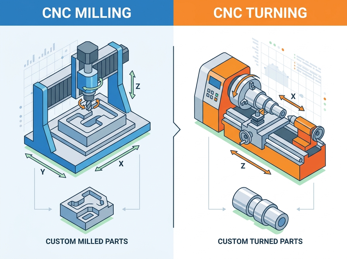
Kinematic Differences: CNC milling relies on a rotating cutting tool moving across a stationary workpiece, while CNC turning rotates the workpiece (stock material) against a stationary cutting tool.
Geometry Dictates Process: Turning is the undisputed standard for axially symmetrical, cylindrical parts; milling is required for prismatic, flat, or complex 3D geometries.
Cost and Setup Trade-offs: Turning generally offers faster cycle times, simpler programming, and lower setup costs for round parts. Milling accommodates higher complexity but requires more extensive programming and multi-axis setups.
Hybrid Capabilities: Modern manufacturing increasingly relies on mill-turn centers (lathes with live tooling) to combine both processes, mitigating the risk of multi-setup alignment errors.
CNC milling primarily utilizes rectangular blocks, plates, or near-net-shape castings as raw stock input. The core of the milling process involves multi-axis movement of the spindle holding the rotating cutting tool. Depending on the machine, this movement can occur across 3-axis, 4-axis, or 5-axis configurations. A standard 3-axis mill moves the tool along the X, Y, and Z axes. Advanced 4-axis machines add rotation along the X-axis (A-axis), allowing for continuous machining of cylindrical features on a prismatic block. Full 5-axis machining adds a fifth axis of rotation (B or C axis), enabling the tool to approach the workpiece from virtually any angle. This capability is essential for complex aerospace components, impellers, and medical implants where undercuts and compound angles are prevalent.
The material removal process relies on specific cutting tools. End mills handle profiling, slotting, and plunging. Face mills remove large amounts of material from flat surfaces quickly. Slot cutters create narrow grooves, while drills and taps handle hole-making operations. The choice of tool dictates the material removal rate (MRR) and the final surface finish. High-speed steel (HSS) tools are common for softer materials, but solid carbide tools dominate modern production due to their rigidity and ability to withstand high cutting temperatures.
Workholding methods directly impact the rigidity and precision of the machining operation. Vises are the most common workholding solution for rectangular stock. Fixtures are custom-designed to hold complex or irregular shapes securely. Vacuum tables are often used for thin, flat plates that might warp or deform under the clamping pressure of a traditional vise. The rigidity of the workholding setup is critical; any vibration or chatter during the milling process will degrade the surface finish and compromise dimensional accuracy.
In contrast, CNC turning primarily utilizes cylindrical bar stock, round tubes, or hexagonal bars fed through a spindle. The mechanics involve a chuck or collet holding the stock material and spinning it at high RPMs. A chuck uses adjustable jaws to grip the material, accommodating a wide range of diameters. Collets provide a 360-degree grip on the stock, offering superior concentricity and clamping force for smaller diameter bars. Bar feeders automate the loading process, pushing a new section of stock into the machining envelope after each part is completed, enabling continuous, unattended production.
Stationary single-point cutting tools, held in a turret, perform facing, grooving, threading, and boring operations as the workpiece rotates. Facing tools square off the end of the stock. Turning tools reduce the outside diameter (OD). Boring bars enlarge internal holes (ID). Threading tools cut internal or external threads. Grooving tools create recesses for O-rings or retaining rings. The turret indexes rapidly between these tools, minimizing non-cutting time.
This continuous cutting action affects chip formation, necessitating chip breakers and efficient heat dissipation strategies. Unlike the interrupted cutting experienced in milling, where the tool teeth enter and exit the material, turning involves continuous engagement. This generates significant heat at the cutting edge. Coolant is directed precisely at the cutting zone to manage temperatures and flush chips away. Chip breakers are molded into the cutting inserts to force the continuous ribbon of metal to curl and break into small, manageable pieces, preventing them from tangling around the workpiece or tooling.
Engineers map CAD features to specific machine kinematics to determine the optimal manufacturing method. Baseline requirements include evaluating concentricity, flatness, runout, and feature accessibility to ensure the chosen process can achieve the desired specifications. A thorough DFM review involves several critical steps.
Analyze the primary geometry: Is the part fundamentally cylindrical or prismatic?
Identify critical tolerances: Which features require the tightest control, and how do they relate to each other?
Evaluate feature accessibility: Can standard cutting tools reach all required surfaces without interference?
Assess workholding requirements: How will the part be held during machining, and will the clamping forces cause deformation?
Determine secondary operations: Will the part require heat treatment, plating, or assembly after machining?
Concentricity and runout are critical metrics for rotating components like shafts and bearings. Turning naturally excels at maintaining these tolerances because the part rotates around a single axis during machining. Flatness and parallelism are key requirements for mating surfaces on prismatic parts, making milling the preferred choice.
CNC milling is ideal for prismatic parts, flat surfaces, asymmetrical shapes, and complex 3D contours. Specific features requiring milling include pockets, slots, keyways, off-center holes, and complex engraved surface textures. Manifolds, brackets, housings, and heatsinks are classic examples of milled components.
Milling is also required when features must be machined on multiple faces of a part. A 5-axis mill can access five sides of a rectangular block in a single setup, ensuring perfect alignment between features on different faces. This capability is invaluable for complex aerospace and medical components where tolerance stacking across multiple setups would result in rejected parts.
CNC turning is ideal for axially symmetrical parts, cylinders, disks, shafts, and bushings. Specific features requiring turning include OD/ID threading, custom tapers, knurling, and concentric grooves. Fasteners, fittings, spacers, and hydraulic cylinders are typical turned components.
Turning is particularly effective for parts with high length-to-diameter ratios, such as long shafts. Tailstocks and steady rests are used to support the free end of the workpiece, preventing deflection and vibration during machining. This ensures consistent diameter and surface finish along the entire length of the part.
Both processes achieve high precision, often reaching tolerances of +/- 0.0005 inches or tighter depending on the machine, material, and tooling. However, the nature of the cutting action influences the achievable surface finish. Turning often achieves superior, highly consistent finishes on cylindrical surfaces due to continuous tool engagement. The single-point tool leaves a fine, helical toolpath that can be controlled by adjusting the feed rate and tool nose radius.
Milling requires specific step-overs and feed rates to achieve smooth finishes on complex 3D profiles. The interrupted cutting action can leave visible witness marks where the tool enters and exits the material. Achieving a mirror-like finish on a milled surface often requires secondary operations like grinding or polishing, whereas a well-tuned lathe can often produce the required finish directly off the machine.
Process | Typical Tolerances | Surface Finish (Ra) | Strengths |
|---|---|---|---|
CNC Turning | +/- 0.0005" to +/- 0.001" | 16 to 63 microinches | Concentricity, continuous finishes on cylinders. |
CNC Milling (3-Axis) | +/- 0.001" to +/- 0.005" | 32 to 125 microinches | Flatness, parallelism, complex pockets. |
CNC Milling (5-Axis) | +/- 0.0005" to +/- 0.002" | 32 to 63 microinches | Complex 3D contours, multi-face alignment. |
Turning is highly effective for high-volume production, especially when integrated with bar feeders for automated, lights-out manufacturing. A Swiss-style lathe, for example, can produce thousands of small, complex cylindrical parts per day with minimal operator intervention. The continuous feeding of bar stock and the rapid indexing of the tool turret result in extremely short cycle times.
Milling is often evaluated for low-to-medium volumes or highly complex, low-yield aerospace and medical components. While pallet pools and robotic loaders can automate milling operations, the setup and programming times are generally longer than for turning. Milling is often the preferred choice for prototyping and low-volume production runs where the flexibility of the process outweighs the higher cycle times.
Turning often utilizes round bar stock closely matching the final OD, minimizing waste and optimizing the stock-to-part ratio. If you need a part with a 1-inch maximum diameter, you start with 1-inch or 1.125-inch bar stock. The material removal is focused on the specific features, leaving the core of the material intact.
Milling from block stock can result in higher material removal rates (MRR) and lower overall material yield. If you are machining a complex bracket from a solid block of aluminum, you might remove 70% or 80% of the original material to achieve the final shape. This high scrap rate must be factored into the overall cost of the part, especially when working with expensive materials like titanium or Inconel.
The programming barrier differs significantly between the two processes. CNC turning is fundamentally simpler, often requiring only 2-axis G-code (X and Z axes), leading to faster programming turnarounds. Many simple turned parts can be programmed conversationally directly at the machine control, without the need for complex CAM software.
Multi-axis milling requires complex CAM programming for toolpath generation, simulation, and strict collision avoidance protocols. A 5-axis milling program must account for the tool, the tool holder, the spindle, the workpiece, and the workholding fixtures to ensure there are no collisions during the machining cycle. This requires skilled programmers and expensive CAM software licenses, adding to the upfront cost of the project.
Setup times impact the final cost per part. Milling often involves multiple operations, requiring the operator to flip the part for secondary operations. Each setup requires indicating the part, setting work offsets, and verifying tool lengths. This labor-intensive process increases the risk of setup errors and tolerance stacking.
Turning frequently completes parts in a single setup, reducing operator intervention and part-handling overhead. A lathe with a sub-spindle can machine the front of the part, transfer it to the sub-spindle, and machine the back of the part without any operator intervention. This "done-in-one" capability significantly reduces labor costs and improves overall part quality.
Single-point carbide lathe inserts used in turning offer distinct cost-efficiency compared to solid carbide multi-flute end mills used in milling. When a lathe insert wears out, you simply index it to a fresh cutting edge. When an end mill wears out, the entire tool must be replaced or reground.
Continuous cutting in turning experiences steadier thermal and mechanical loads, leading to more predictable tool life than the interrupted cutting in milling. The constant hammering of the tool teeth entering and exiting the material in milling can lead to premature tool failure, especially in hard or abrasive materials. This requires more frequent tool changes and increases the overall tooling cost per part.
Designing monolithic parts that require complex 5-axis milling can inflate costs. Sometimes, a redesigned 2-part turned and assembled configuration would be significantly cheaper. Engineers often default to complex milled designs without considering the manufacturing implications. Implement strict DFM reviews prior to finalizing CAD models to ensure compatibility with standard tooling profiles.
For example, a complex housing with internal fluid channels might require expensive 5-axis milling and deep hole drilling. Redesigning the housing as two separate turned components that are bolted or welded together could reduce the machining time by 50% and eliminate the need for specialized tooling.
Moving a part from a lathe to a mill for secondary operations introduces risks like loss of concentricity, datum shifts, and setup errors. Every time a part is unclamped and reclamped, there is a potential for misalignment. Specify vendors that utilize advanced Mill-Turn (Hybrid) Machining Centers with live tooling to complete complex custom milled and turned parts in a single setup.
A mill-turn center combines the turning capabilities of a lathe with the milling capabilities of a machining center. Live tooling allows the machine to perform drilling, tapping, and milling operations on the face or OD of the part while it is still held in the chuck. This eliminates the need for secondary setups and ensures perfect alignment between the turned and milled features.
Evaluate shops based on their machine list, including multi-axis mills and live-tooling lathes. Assess their inspection capabilities, material specialization, and relevant certifications like ISO 9001 or AS9100. A shop with a diverse range of equipment can route your parts to the most efficient machine, reducing costs and lead times.
Inspection capabilities are equally important. A shop must have the metrology equipment necessary to verify the tolerances specified on your drawings. Coordinate Measuring Machines (CMMs), optical comparators, and surface roughness testers are essential tools for ensuring part quality. Certifications like ISO 9001 demonstrate a commitment to quality management systems and continuous improvement.
The choice between CNC milling and turning is rarely a matter of preference; it is dictated by part geometry, required concentricity, and production volume. Default to turning for cylindrical, high-volume parts to leverage lower costs and faster cycle times. Reserve milling for prismatic, complex geometries. For parts requiring both, seek vendors with advanced mill-turn capabilities.
Audit your current CAD files for DFM optimization, identifying features that drive up machining costs.
Consolidate your vendor list based on multi-axis capabilities and inspection equipment.
Submit your designs to a qualified machining partner for a comprehensive manufacturability review and quote.
Evaluate the potential for redesigning complex monolithic parts into simpler turned and assembled components.
A: Turning generally offers lower setup and programming costs for cylindrical parts due to simpler kinematics and continuous cutting. Milling is typically more expensive for complex geometries due to multi-axis programming, longer setup times, and higher tooling costs.
A: Yes, modern CNC lathes equipped with live tooling (mill-turn centers) can perform milling operations like drilling, tapping, and slotting on a turned part without requiring a separate machine setup.
A: Both processes can achieve extremely tight tolerances (+/- 0.0005 inches or better). Turning is generally better for concentricity and cylindrical tolerances, while milling excels at holding tight tolerances across complex 3D profiles and flat surfaces.
A: If the part is primarily cylindrical or axially symmetrical, turning is the best choice. If the part is prismatic, block-like, or features complex 3D contours, off-center holes, or flat surfaces, milling is required.
A: Both processes handle a wide range of materials, including aluminum, stainless steel, titanium, brass, and engineering plastics. The choice depends on the application requirements rather than the machining process itself.
A: A mill-turn machine combines a lathe's turning capabilities with a mill's rotating tools. It is necessary for complex parts requiring both cylindrical and prismatic features, allowing completion in a single setup to eliminate alignment errors.
A: Turning is highly efficient for high-volume production, especially with automated bar feeders. Milling is often better suited for low-to-medium volumes or highly complex parts where the setup time is justified by the part's value.


