


close
Choose Your Site
Global
Social Media
Views: 0 Author: Site Editor Publish Time: 2026-07-15 Origin: Site


Achieving tight tolerances and superior surface finishes in modern manufacturing relies entirely on precise mathematical calculation, geometric understanding, and thermal management. Operator intuition simply does not cut it anymore. Incorrect feed rates carry a heavy cost on the shop floor. You face premature tool wear, catastrophic tool failure, poor surface finish, scrapped workpieces, and compromised project economics. Mastering speeds and feeds forms the critical baseline for evaluating any manufacturing partner. This guide provides a definitive framework for calculating feed rates and understanding the physical variables involved. We will show you how to ensure the production of high-precision CNC machined parts. By mastering these calculations, engineers and machinists optimize material removal rates while protecting expensive tooling and maintaining strict dimensional accuracy.
Mathematical Baseline: Feed rate (Inches Per Minute or mm/min) is a direct product of Spindle Speed (RPM), Number of Flutes (Teeth), and Chip Load (Feed per Tooth).
The "Speed" vs. "Feed" Distinction: Speed (RPM) dictates the cutting edge velocity, while Feed (IPM/MMPM) controls the tool's linear advancement through the material.
Manufacturer Data is the Anchor: Theoretical formulas require baseline data; always start with the tooling manufacturer’s recommended Surface Feet per Minute (SFM) and chip load, often found directly on the back of the insert pack or in tooling catalogs.
Digital Validation: Manual calculations should be cross-referenced with reputable speeds and feeds calculators (e.g., Kennametal, Haas, or Machinist Calculator Pro) to eliminate human error.
The Rigidity Variable: Theoretical feed rates must be adjusted based on the physical realities of the machine setup, including spindle runout, workholding stability, and tool stick-out.
Commercial Impact: Optimizing feed rates is a balancing act between Material Removal Rate (MRR) and tool life, directly dictating the cost and quality of high-precision CNC machined parts.
Before calculating the final feed rate, engineers must define the foundational variables and physical concepts that dictate how the cutting tool interacts with the workpiece. Understanding these elements is mandatory for maximizing your precision CNC machining capabilities. You cannot program a toolpath effectively without knowing exactly what happens at the cutting edge.
Cutting speed refers to the rotational velocity of the spindle. Feed rate represents the linear movement of the machine table. These two movements interact to form the actual path of the tool tooth through the material. Balancing them correctly ensures efficient cutting rather than destructive rubbing. If your speed is too high and your feed is too low, you generate massive amounts of heat. This heat transfers directly into the tool and the workpiece, causing rapid failure.
When you walk onto a shop floor, you hear the difference between a good cut and a bad cut. A proper feed rate produces a smooth, consistent sound. A feed rate that is too low produces a high-pitched squeal, indicating rubbing. A feed rate that is too high sounds like heavy thumping, indicating the machine is struggling to push the tool through the material.
Surface Feet per Minute (or meters per minute) represents the speed at which the outer cutting edge moves through the material. Material hardness and tool composition dictate the maximum allowable SFM. Carbide tools handle much higher SFM than High-Speed Steel (HSS) tools. You must match the SFM to the specific alloy you are cutting.
Workpiece Material | Tool Material | Recommended SFM Range |
|---|---|---|
Aluminum (6061-T6) | Solid Carbide | 800 - 1200 |
Low Carbon Steel (1018) | Solid Carbide | 300 - 500 |
Stainless Steel (304) | Solid Carbide | 150 - 300 |
Titanium (Ti-6Al-4V) | Solid Carbide | 100 - 200 |
The table above shows baseline starting points. You always adjust these numbers based on the specific tool coating and the rigidity of your setup. Running titanium at 800 SFM will instantly melt the cutting edge of a carbide endmill. Running aluminum at 100 SFM wastes machine time and reduces profitability.
Spindle speed is calculated using the standard formula: RPM = (SFM × 3.82) / Tool Diameter. There is an inverse relationship between tool diameter and RPM. Smaller tools require higher RPMs to achieve the same SFM as larger tools. A 0.125-inch endmill needs significantly more RPM than a 1.0-inch endmill to maintain the same surface speed.
If your machine has a maximum spindle speed of 10,000 RPM, you might not be able to achieve the optimal SFM for very small micro-tools in soft materials like aluminum. In these cases, you must run the spindle at its maximum safe speed and recalculate your feed rate based on that actual RPM, rather than the theoretical ideal RPM.
Chip load is the physical thickness of the material removed by a single cutting edge in one revolution. The chip plays a vital role in evacuating heat from the cutting zone. Proper chip load prevents work hardening and tool degradation. When a tool cuts, it shears the material. This shearing action generates heat. A thick, properly formed chip absorbs that heat and carries it away from the tool and the part as it evacuates the flute.
If your chip load is too thin, the heat stays in the tool. The cutting edge breaks down rapidly. In materials like 304 stainless steel, a thin chip load causes the surface of the material to work-harden. The next tooth that comes around hits a hardened surface, leading to catastrophic tool failure.
Machinists and CAM programmers use a sequential calculation process to move from raw material data to finalized code. Following these steps ensures accurate and safe toolpaths. You do not guess these numbers. You calculate them systematically.
Locate Tooling Parameters: The most reliable starting point for any job is the back of the insert pack or the manufacturer's tooling catalog. Read the manufacturer's engraving or labeling to identify the exact tool geometry and recommended starting SFM and IPT (Inches Per Tooth). Tool manufacturers spend millions of dollars testing their products. Use their data.
Establish the Baseline RPM: Calculate the RPM based on the catalog or insert pack SFM. Use the standard Imperial formula: RPM = (SFM × 3.82) / Tool Diameter. For metric applications, use: RPM = (Vc × 1000) / (π × Tool Diameter). Write this number down.
Apply the Feed Rate Formula: The core formula is: Feed Rate = RPM × Number of Flutes × Chip Load. For example, a 0.5-inch, 4-flute carbide end mill cutting 6061 Aluminum with a chip load of 0.004 inches at 3000 RPM requires a feed rate of 48 IPM (3000 × 4 × 0.004).
Metric vs. Imperial Conversions: Global manufacturing standards often require conversions between Inches Per Minute (IPM) and Millimeters Per Minute (mm/min). Multiply IPM by 25.4 to get mm/min, or divide mm/min by 25.4 to get IPM. Ensure your CAM software is set to the correct unit system before outputting G-code.
Cross-Reference and Verify with Digital Calculators: Use digital speeds and feeds calculators to validate manual math. Using multiple data points ensures accuracy before running a tool path on expensive stock, preventing costly programming errors. A simple decimal point error in your manual math will crash a machine.
Let us look at a more complex example. You are machining a block of 4140 steel using a 0.375-inch, 5-flute coated carbide endmill. The manufacturer recommends 400 SFM and a chip load of 0.0025 inches per tooth. First, calculate the RPM: (400 × 3.82) / 0.375 = 4074 RPM. Next, calculate the feed rate: 4074 RPM × 5 flutes × 0.0025 IPT = 50.9 IPM. You program your machine to run at 4074 RPM and 51 IPM.
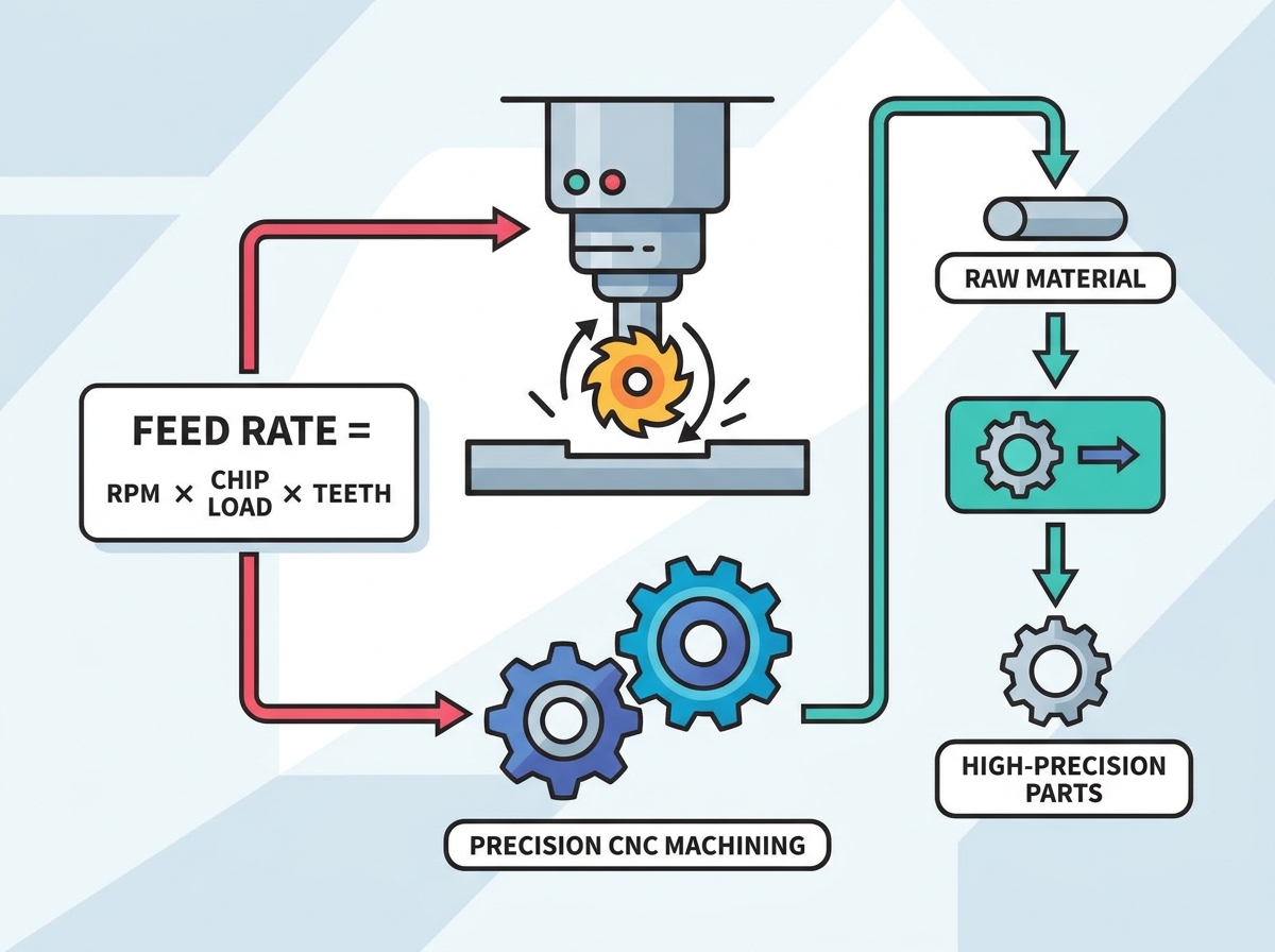
Different materials and tool geometries force adjustments to baseline calculations to maintain precision. Engineers must evaluate these dynamics carefully. You cannot use the same cutting strategy for every job that comes across your desk.
Feed rate strategies differ significantly between non-ferrous metals like aluminum and tough alloys like titanium or Inconel. Aluminum is soft and gummy. It requires high speeds, high feeds, and tools with fewer flutes to allow for massive chip evacuation. If chips pack into the flutes, the tool snaps.
When machining stainless steels or high-temp alloys, a feed rate that is too low risks work-hardening the material by rubbing instead of cutting. You must maintain a heavy enough chip load to get under the work-hardened layer left by the previous pass. This requires rigid machines and high-quality tool holders to handle the increased cutting forces without chattering.
Flute count impacts feed rate directly. A 2-flute tool provides better chip evacuation for aluminum, while a 4-to-6 flute tool yields better surface finishes in steel. More flutes mean you can feed faster at the same RPM, because there are more cutting edges engaging the material per revolution.
Advanced tool coatings like TiAlN or AlTiN allow for higher SFM and feed rates by mitigating thermal shock. These coatings act as a thermal barrier, keeping the heat in the chip and out of the carbide substrate. When running coated tools in steel, you often run dry (using air blast instead of coolant) to prevent thermal cracking of the coating.
The engagement angle of the tool alters the effective chip thickness. Radial Chip Thinning occurs during light radial cuts, requiring feed rates to be increased to maintain the target chip load and prevent premature tool wear. If your radial depth of cut is less than 50% of the tool diameter, the actual chip thickness is less than your programmed feed per tooth.
Radial Engagement (% of Tool Dia) | Feed Multiplier (Approximate) |
|---|---|
50% | 1.00 |
30% | 1.10 |
10% | 1.70 |
5% | 2.30 |
If you program a 0.004 IPT chip load, but you are only taking a 10% radial step-over, your actual chip thickness might only be 0.0023 inches. The tool will rub, generate heat, and wear out quickly. You must multiply your programmed feed rate by the chip thinning factor to achieve the actual desired chip thickness.
Engineers must make commercial and operational trade-offs when programming toolpaths. Balancing speed and quality is essential for profitable manufacturing. You evaluate every toolpath based on its impact on the overall production cycle.
MRR is defined as Feed Rate × RDOC × ADOC. Aggressive feed rates lower cycle times but can lead to premature tool replacement and machine downtime. Finding the optimal balance is key to cost-effective production. Pushing a tool to its absolute limit might save 30 seconds per part, but if you have to stop the machine every 10 parts to change a broken endmill, you lose money.
You track tool life in minutes in the cut. If a $100 endmill lasts 60 minutes at a moderate feed rate, but only 15 minutes at an aggressive feed rate, you calculate the cost of the tool against the value of the machine time saved. Usually, a stable, predictable process is more profitable than a highly aggressive, unstable one.
Excessive feed rates increase cutting forces, leading to tool deflection. Deflection causes dimensional inaccuracies, directly threatening the quality of the final parts and compromising tight tolerances. When a tool deflects, it bends away from the cut. The resulting part will have tapered walls or oversized features.
To combat deflection, you use the shortest possible tool stick-out. You hold the tool deep in the collet or shrink-fit holder. If you must use a long tool to reach a deep pocket, you must reduce your feed rate and take lighter depths of cut to minimize the lateral forces pushing against the tool.
Finishing passes require significantly different feed rate calculations than roughing passes. The relationship between feed rate, tool nose radius, and the resulting surface roughness (Ra) dictates the final visual and functional quality of the part. Roughing operations prioritize maximum MRR. You push the tool hard to remove bulk material quickly.
Finishing operations prioritize surface finish and dimensional accuracy. You increase the spindle speed and decrease the feed rate. You leave a small, consistent amount of material (e.g., 0.010 inches) on the walls and floor for the finishing tool to remove. This ensures the finishing tool experiences a constant cutting force, preventing deflection and leaving a mirror-like finish.
There is often a gap between textbook math and physical machining realities. Identifying and mitigating these risks ensures successful production runs. You must adapt your theoretical numbers to the actual conditions of your machine and setup.
Older or lighter-duty CNC machines cannot handle the feed rates calculated for rigid, industrial-grade machining centers. A lightweight machine will vibrate violently if you try to push a 1-inch endmill through steel at maximum feed. You must scale back your parameters to match the horsepower and mass of your specific machine.
Spindle runout causes uneven chip loads, leading to micro-chipping of the tool edge and poor surface finish. If your spindle has 0.001 inches of runout, one tooth of a 4-flute endmill will take a massive chip, while the opposite tooth takes almost nothing. This destroys the tool rapidly. Check your spindle and tool holders with a dial indicator regularly.
Thin-walled parts or suboptimal clamping require reduced feed rates to prevent chatter and harmonic vibration. A rigid setup is mandatory for achieving calculated feed rates safely. If the part vibrates during the cut, the tool will chip. You use soft jaws, custom fixtures, and proper clamping techniques to secure the workpiece solidly to the machine table.
If you hear chatter, you must intervene immediately. Chatter is a self-exciting vibration that will destroy the tool and scrap the part. You stop the machine, adjust the spindle speed up or down by 10%, or reduce the feed rate until the vibration stops.
Blindly trusting CAM software default speeds and feeds is dangerous. Software defaults are often generic and do not account for your specific setup rigidity or tool stick-out. Machinist overrides are necessary. You utilize feed rate override dials (FRO) during the first article inspection to dial in the perfect cut based on real-time feedback.
A skilled machinist watches the load meter on the CNC control. If the spindle load spikes unexpectedly, they dial back the feed rate. They look at the color and shape of the chips. Silver chips in steel indicate good heat evacuation. Blue or purple chips indicate excessive heat. They adjust the parameters at the machine and update the CAM program for the next run.
Calculating CNC feed rate begins with the relationship between spindle speed, flute count, and chip load, but the theoretical result should be treated as a starting point rather than a fixed production setting.
Tool-manufacturer recommendations provide the most reliable baseline for cutting speed and chip load. These values must then be adjusted for workpiece material, tool diameter and coating, radial and axial engagement, machine rigidity, tool overhang, workholding stability, and required surface finish. Radial chip thinning should also be considered during light engagement cuts to prevent rubbing and excessive heat.
During first-article machining, spindle load, chip formation, vibration, dimensional accuracy, and surface quality should be monitored before finalizing the program. The optimal feed rate balances material removal, tool life, process stability, and part quality—not maximum machine speed alone.
A: A feed rate that is too slow causes the tool to rub against the material rather than cut it. This generates excessive heat, leads to work hardening in certain metals, and causes premature tool dulling. It also wastes valuable machine time and reduces overall shop profitability.
A: Excessive feed rates increase cutting forces significantly. This results in tool breakage, severe tool deflection, poor surface finish, and potential damage to the machine spindle. It can also pull the workpiece out of the vise or fixture, causing a catastrophic crash.
A: The most accurate source for chip load data is the back of the tool's insert pack or the specific tool manufacturer's catalog. These provide baseline recommendations based on extensive testing. Always start with the manufacturer's data before making adjustments at the machine.
A: Yes, apps like Machinist Calculator Pro or manufacturer-specific calculators provide quick, reliable secondary validation to cross-reference your manual calculations. They help prevent simple math errors that could lead to broken tools or scrapped parts.
A: Radial chip thinning is a geometric phenomenon occurring during light radial cuts where the actual chip thickness is less than the programmed feed per tooth. You must increase the programmed feed rate to compensate and maintain the target chip load, preventing tool rubbing.
A: No. Roughing prioritizes high material removal rates and maintaining proper chip load, requiring higher feed rates. Finishing prioritizes lower feed rates and specific tool engagement to achieve superior surface quality and hold tight dimensional tolerances.


