


close
Choose Your Site
Global
Social Media
Views: 0 Author: Site Editor Publish Time: 2026-07-22 Origin: Site


Producing complex, high-tolerance parts on traditional 3-axis machines creates a massive operational bottleneck on the shop floor. Every time a machinist manually repositions a workpiece for a new angle, the setup introduces tolerance stack-up. This drives up labor expenses and extends lead times. Engineering and procurement teams constantly struggle to balance the high hourly rates of advanced machining with the strict necessity for precision, repeatability, and reduced time-to-market for complex geometries.
Transitioning to 5-axis CNC machining services is a strategic manufacturing capability, not just a mechanical upgrade. Understanding the technical mechanics, cost trade-offs, and provider capabilities is essential for effectively sourcing these services. By leveraging continuous multi-axis motion, manufacturers consolidate operations, mitigate alignment errors, and produce highly intricate parts that would otherwise be impossible or economically unviable.
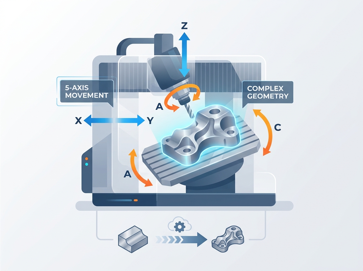
Technical Capability: 5-axis machining utilizes three linear axes (X, Y, Z) and two rotational axes (A, B, or C) to approach a workpiece from nearly any angle, drastically reducing the need for multiple manual setups.
Cost-Benefit Threshold: While the hourly rate for 5-axis services is higher than 3-axis, the consolidation of operations often results in a lower cost-per-part for complex geometries and mid-to-high volume production runs.
Provider Evaluation: Sourcing reliable 5-axis CNC machining services requires auditing a partner’s CAM programming expertise, machine kinematics (trunnion vs. swivel head), and in-house metrology (CMM) capabilities.
Risk Management: The primary risks in 5-axis procurement involve CAM simulation errors, tool deflection on deep pockets, and inadequate quality validation—all of which require strict vendor vetting.
Traditional milling centers operate on three linear axes. The cutting tool moves left and right along the X-axis, forward and backward along the Y-axis, and up and down along the Z-axis. While effective for simple prismatic parts, this configuration restricts the tool to a single vector of approach. To machine undercuts or compound angles, the operator must stop the machine, unclamp the part, rotate it, and re-indicate the fixture. This wastes time and introduces error.
5-axis machining eliminates this limitation by introducing two additional rotary axes. The A-axis rotates around the X-axis, the B-axis rotates around the Y-axis, and the C-axis rotates around the Z-axis. Depending on the machine design, a 5-axis center will utilize a combination of two of these rotary axes. Often, you see A and C, or B and C configurations. These axes interact simultaneously. They manipulate the cutting tool, the workpiece, or both. This allows the end mill to access five sides of a part in a single setup.
Not all 5-axis machines are built the same. The physical arrangement of the rotary axes dictates the types of parts the machine can efficiently handle. We call this machine kinematics.
Configuration | Rotary Axis Location | Best Applications | Key Advantages |
|---|---|---|---|
Table-Table (Trunnion) | Both in the table (Workpiece moves) | Smaller to medium parts, heavy cuts | High torque, excellent rigidity for hard metals |
Head-Head (Swivel Head) | Both in the spindle (Tool moves) | Large, heavy components (e.g., aerospace frames) | Handles massive parts without compromising dynamics |
Head-Table (Mixed) | One in spindle, one in table | Diverse part profiles, deep cavities | Highly versatile, excellent tool clearance |
Understanding the distinction between simultaneous and positional machining is critical when evaluating project requirements. You need to know what you are paying for.
Positional 5-axis, commonly referred to as 3+2 machining, utilizes the rotary axes to lock the workpiece into a specific, fixed angle. Once locked, the cutting tool executes standard 3-axis movements to machine the feature. This method is highly efficient for flat features, holes, and pockets located at compound angles. It provides excellent rigidity and allows for aggressive material removal rates.
Continuous or simultaneous 5-axis machining involves the synchronized movement of all five axes during the cutting process. The tool continuously changes its orientation relative to the workpiece as it moves along the toolpath. You must specify continuous 5-axis machining for complex, organic contoured surfaces. Think of aerospace impellers, turbine blades, or advanced medical implants. The tool must smoothly follow a sweeping 3D curve without stopping.
Certain industries demand geometries that simply cannot be produced efficiently on 3-axis equipment. Aerospace applications frequently require impellers and blisks featuring overlapping, twisted blades. Medical device manufacturing relies on 5-axis capabilities to produce anatomical implants and prosthetics with organic, non-uniform contours. Automotive engineering utilizes the technology for optimized intake manifolds and cylinder heads.
For these applications, continuous 5-axis motion is non-negotiable. It maintains optimal tool-to-workpiece engagement at all times. By dynamically adjusting the tool vector, the machine prevents the shank of the cutting tool from gouging adjacent surfaces on complex curves. This ensures the exact replication of the CAD model.
Every manual setup introduces a margin of error. If a part requires six operations on a 3-axis mill, the machinist must align the part six separate times. Even with highly accurate fixtures, these microscopic alignment errors accumulate.
Setup Reduction: Sourcing 5-axis CNC machined components drastically reduces physical setups, often achieving "Done-in-One" machining.
Datum Retention: By keeping the part clamped in a single zero-point workholding system, the spatial relationship between all machined features remains perfectly intact.
GD&T Compliance: This is critical for meeting strict true position requirements and ensuring full compliance with complex geometric dimensioning and tolerancing callouts.
Surface finish quality is directly tied to tool rigidity. On a 3-axis machine, reaching the bottom of a deep cavity often requires an exceptionally long end mill. Long tools are prone to vibration and deflection. This causes chatter marks on the machined surface and compromises dimensional accuracy.
5-axis machines allow the cutting tool or the workpiece to tilt. This provides access to deep cavities with much shorter, more rigid cutting tools. Shorter tools reduce vibration and deflection significantly. This stability results in tighter tolerances and superior surface finishes straight off the machine. It minimizes or entirely eliminates the need for secondary manual polishing operations.
When vetting a manufacturing partner, you must evaluate their specific equipment. Assess the age of the machines, maximum spindle speeds, and overall structural rigidity. High-speed spindles are necessary for efficient aluminum removal. High-torque, rigid spindles are required for tough alloys like Inconel.
Pay close attention to thermal stability. Long run cycles generate significant heat, causing machine components to expand and shift. Top-tier providers utilize machines with integrated linear scales and active thermal compensation systems. This combats thermal expansion, ensuring the first part of the day matches the last part of the day.
5-axis hardware is only as capable as the software and the machinist driving it. Generating simultaneous 5-axis toolpaths requires advanced CAM software, such as Mastercam or HyperMill. The programming process is highly complex. The programmer must manage tool vectors, gouge avoidance, and machine axis limits simultaneously.
Furthermore, dedicated digital twin simulation and g-code verification software is mandatory. This software simulates the exact kinematics of the specific machine tool. It verifies axis limit boundaries and detects potential collisions between the spindle, tool, fixture, and machine structure before running the physical part. A provider lacking robust simulation capabilities poses a severe risk to your project timeline.
Producing complex 5-axis components requires equally advanced inspection capabilities. Standard hand tools are insufficient for verifying complex 3D contours and true position across multiple planes.
Require your provider to utilize 5-axis Coordinate Measuring Machines (CMM) equipped with scanning probes. Multi-sensor laser scanning can also rapidly verify complex surface profiles against the original CAD model. For critical industries like aerospace, the provider must be capable of generating comprehensive, AS9102-compliant First Article Inspection (FAI) reports. This validates the entire manufacturing process.
Procurement teams must acknowledge the higher initial Non-Recurring Engineering (NRE) costs associated with 5-axis machining. Complex CAM programming, custom fixture design, and virtual simulation runs require highly skilled labor and significant time upfront.
However, these upfront costs are quickly amortized over production runs. Because 5-axis machining consolidates operations, the cycle time per part drops. Manual labor costs decrease significantly. This dynamic makes 5-axis highly economical for recurring orders and mid-to-high volume production scaling.
Not every part requires 5-axis capabilities. Simple prismatic parts, components with single-plane features, or parts requiring only one or two setups are generally more cost-effective to produce on standard 3-axis equipment.
The breakeven point occurs when the reduction in setup time, labor intervention, and complex fixture costs outweighs the higher hourly machine rate of a 5-axis center. If a part requires four or more setups on a 3-axis mill, or involves complex angled holes that would require custom sine plates, moving the job to a 5-axis machine will almost always yield a lower total cost per part.
While 5-axis is the standard for complex parts, 7-axis machining exists for highly specialized applications. 7-axis machining typically adds linear movement along the tool axis and rotational movement of the workpiece itself. You often see this in advanced Swiss-style lathes or mill-turn centers.
This technology is typically reserved for highly specialized, long-slender parts, such as aerospace landing gear or complex medical screws. For the vast majority of structural components, brackets, and housings, 7-axis machining is overkill. Standard 5-axis applications provide the optimal balance of capability and cost.
Machining exotic alloys like Inconel, Titanium, and Cobalt-Chrome on 5-axis setups presents distinct challenges. These materials generate extreme heat and cutting forces.
Aggressive toolpaths can easily lead to tool deflection if the provider lacks experience with specific material machinability ratings. Deflection causes dimensional inaccuracies and poor surface finish. Mitigate this risk by selecting providers who utilize specialized tooling coatings, optimized trochoidal milling strategies, and rigid workholding designed specifically for hard metals.
Outsourcing proprietary designs carries inherent risks regarding intellectual property theft or data breaches. When selecting a service provider, you must verify their compliance frameworks.
Ensure the vendor maintains strict ITAR compliance if handling defense-related components. Verify their ISO 9001 or AS9100 certifications to confirm they adhere to standardized quality management systems. Secure data handling protocols, encrypted file transfers, and strict NDA enforcement are mandatory prerequisites before sharing any CAD data.
Machine downtime or a lack of redundancy at a vendor's facility can instantly derail your production schedules. A single crashed spindle on a 5-axis machine can result in weeks of downtime.
Recommend auditing a provider’s machine capacity and redundancy. Do they have multiple identical machines to absorb unexpected downtime? Review their preventative maintenance schedules and assess their raw material sourcing networks to ensure they can consistently meet your lead time requirements.
5-axis CNC machining stands as the definitive solution for manufacturing complex, high-precision components where traditional multi-setup machining introduces unacceptable risk, excessive cost, or quality degradation. By utilizing simultaneous multi-axis motion, manufacturers achieve superior accuracy, eliminate tolerance stack-up, and drastically reduce cycle times. The most reliable service providers combine rigid machine kinematics, elite CAM programming expertise, and rigorous in-house metrology.
To move forward effectively, take these next steps:
Finalize 3D CAD models with clear geometric requirements.
Define critical GD&T callouts accurately on 2D drawings.
Establish realistic volume expectations for production scaling.
Initiate RFQs exclusively with vetted, certified manufacturing partners who demonstrate proven 5-axis competency.
A: 3+2 machining locks the two rotary axes into a fixed position to machine angled features using standard 3-axis movements. Continuous 5-axis machining moves all five axes simultaneously, allowing the cutting tool to smoothly follow complex, sweeping 3D contours without stopping.
A: Costs vary heavily based on part complexity, material selection, and production volume. While the hourly machine rate for 5-axis equipment is higher than 3-axis, this is frequently offset by drastically reduced setup times, lower fixture costs, and decreased manual labor.
A: 5-axis machines process a wide range of materials, including aerospace-grade aluminum, titanium, stainless steel, Inconel, and advanced engineering plastics like PEEK. The specific machine's rigidity and spindle torque dictate its effectiveness with harder alloys.
A: It significantly reduces the need for manual finishing by allowing the use of shorter, more rigid tools that produce superior surface finishes. However, components requiring specific aesthetic polishes or ultra-low Ra requirements may still require secondary finishing processes.
A: The aerospace, defense, medical device, automotive, and energy sectors benefit the most. These industries frequently require components with complex organic geometries, strict GD&T tolerances, and materials that are difficult to machine using traditional multi-setup methods.
A: Provide native 3D CAD files like STEP or IGES formats alongside detailed 2D PDF drawings. The 2D drawings must clearly call out critical tolerances, specific GD&T requirements, threaded hole specifications, and required surface finishes to ensure accurate programming and inspection.


