


close
Choose Your Site
Global
Social Media


While Computer Numerical Control (CNC) milling is a ubiquitous subtractive manufacturing process, the gap between basic machining and aerospace-grade precision is vast. Engineers and procurement teams often face budget overruns, delayed lead times, or out-of-spec components due to a mismatch between part complexity and the chosen machining capability. Navigating these challenges requires a deep understanding of how machine kinematics, tooling, and material science intersect on the shop floor.
This guide serves not just as a technical definition of the milling process, but as a strategic framework for evaluating machine capabilities, material constraints, and selecting the right partner for manufacturing custom components. By understanding the mechanics behind the spindle, you can optimize designs for manufacturability, reduce cycle times, and ensure consistent quality across production runs.
CNC milling utilizes computerized controls and rotating multi-point cutting tools to progressively remove material, achieving tighter tolerances than most additive manufacturing methods.
The choice between 3-axis, 4-axis, and 5-axis milling directly dictates part complexity, fixturing costs, and overall production speed.
Material machinability—ranging from soft aluminums to hardened tool steels or engineering plastics—fundamentally alters spindle speeds, tooling wear, and final unit economics.
Evaluating precision CNC milling services requires looking beyond hourly machine rates to assess their Design for Manufacturability (DFM) feedback, quality control (GD&T) rigor, and industry certifications (e.g., ISO 9001, AS9100).
CNC milling operates on the core principle of subtractive manufacturing. The process begins by securing a raw block of material, known as the workpiece or stock, to a stationary table. A rotating cutting tool then moves across multiple axes to selectively remove material. Unlike additive processes that build parts layer by layer, or formative processes that force material into a mold, milling relies on intermittent cutting forces. This physical interaction generates distinct chip formations and significant heat. Managing this heat requires precise control of tool engagement, feed rates, and coolant application—whether flood, mist, or through-spindle—to maintain dimensional stability and prevent work-hardening of the base material.
The physics of chip formation dictate the success of the cut. As the cutting edge shears the material, it transfers heat into the chip, which is then evacuated from the cutting zone. If chip evacuation fails, the tool recuts the chips, leading to rapid tool wear, poor surface finish, and potential catastrophic tool failure. Understanding these mechanics allows machinists to optimize toolpaths for maximum material removal rates without compromising the integrity of the final part.
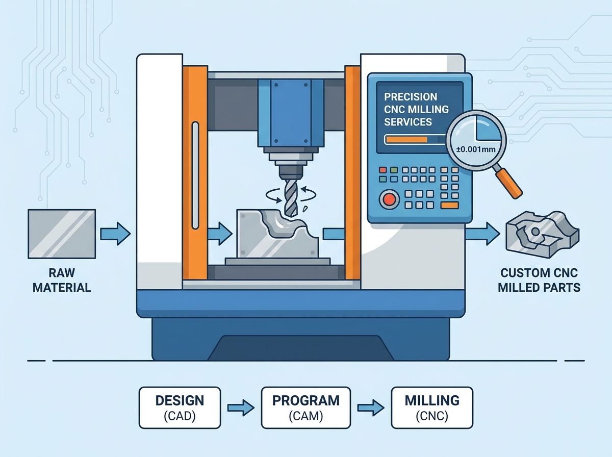
Modern machining relies on a strict digital-to-physical workflow to ensure accuracy and repeatability across batches.
CAD Modeling: Engineers design the 3D model, specifically incorporating manufacturing constraints such as standard corner radii, draft angles, and accessible tool paths.
CAM Programming: Manufacturing engineers translate the CAD file into toolpaths using Computer-Aided Manufacturing software. This step involves selecting cutting tools, calculating step-overs, determining depth of cut, and optimizing feed rates based on material properties.
G-Code Generation & Translation: The CAM software converts the toolpaths into machine-readable G-code, which dictates exact coordinate movements, and M-code, which controls machine functions like coolant flow, pallet changes, and spindle activation.
Machine Setup: Operators calibrate work coordinate systems (WCS) using edge finders or spindle probes, load the raw stock into the workholding device (vises, chucks, or custom fixtures), and install the physical tooling into the machine's automatic tool changer (ATC).
Execution & Monitoring: The machine executes the program autonomously. Advanced systems utilize real-time feedback loops, spindle load monitoring, and probing cycles to monitor tool wear, adjust offsets, and verify dimensions during the cut.
Understanding the distinction between milling and turning dictates process selection and routing on the shop floor. Milling rotates the cutting tool against a stationary part, making it ideal for flat surfaces, slots, pockets, asymmetric profiles, and complex prismatic geometries. Conversely, turning rotates the workpiece against a stationary tool, which is optimal for cylindrical, concentric, or axisymmetric components like shafts, pins, and flanges.
Modern manufacturing often utilizes mill-turn centers. These multi-tasking machines combine both capabilities, allowing shops to produce highly complex custom CNC milled parts in a single setup. By eliminating the need to move a part from a lathe to a mill, these machines drastically reduce handling time, eliminate tolerance stack-up from multiple setups, and improve overall concentricity.
Selecting the right manufacturing process requires weighing setup time, material properties, and production volume.
Process | Setup Time | Material Properties | Geometric Freedom | Ideal Production Volume |
|---|---|---|---|---|
CNC Milling | Moderate to High | Excellent (Isotropic) | High (with 5-axis) | Low to Medium |
CNC Turning | Low to Moderate | Excellent (Isotropic) | Limited to Cylindrical | Low to High |
3D Printing (FDM/SLA) | Very Low | Poor to Moderate (Anisotropic) | Very High (Internal voids) | Prototyping to Low |
Injection Molding | Very High (Tooling) | Good (Isotropic) | Moderate (Requires draft) | Very High |
When comparing milling to 3D printing, milling typically requires higher initial setup times and programming effort. However, milling delivers superior material properties, offering isotropic strength compared to the anisotropic weaknesses often found in printed parts. For low-to-medium volumes, milling provides unmatched geometric accuracy and surface finish. Compared to injection molding or die casting, milling avoids massive upfront tooling lead times and mold investments. It offers a rapid, direct-from-file solution that remains highly adaptable to design revisions.
The number of axes on a milling machine defines its geometric capabilities, operational efficiency, and the types of parts it can produce economically. 3-axis milling remains the industry standard for simpler, flat-profile parts. The tool moves along the X, Y, and Z axes. However, 3-axis machines struggle with deep undercuts and often require manual repositioning for multi-sided parts. This multiple-setup approach increases labor, extends cycle times, and introduces the risk of tolerance stack-up every time the part is unclamped and reclamped.
4-axis machining introduces rotation, typically on the X-axis (A-axis) or Y-axis (B-axis). This allows for continuous machining on cylindrical profiles and enables multi-sided operations without manual refixturing. A common application is machining features on the outside diameter of a cylinder or drilling radial holes, improving both speed and concentricity.
5-axis machining offers the highest level of capability. 5-axis indexed (3+2) machining locks the cutting tool in a fixed angle while the table rotates, allowing standard 3-axis toolpaths to be executed on multiple faces of a part in a single setup. 5-axis continuous machining moves all five axes simultaneously. This technology reduces setup time, eliminates stack-up tolerances from manual repositioning, and enables the creation of complex organic geometries like impellers, turbine blades, and defense-grade enclosures. It also allows the use of shorter, more rigid cutting tools, which reduces vibration and improves surface finish.
Tool selection directly impacts feature resolution, material removal rates, and cycle time. Machinists maintain extensive tool libraries to handle diverse geometries.
Tool Type | Primary Application | Key Advantage |
|---|---|---|
Flat End Mill | Flat surfaces, vertical walls, 90-degree corners | High material removal rate for standard pockets. |
Ball Nose End Mill | 3D surfacing, organic contours, large internal radii | Leaves a smooth finish on complex 3D topographies. |
Face Mill | Surface facing, establishing flat datum surfaces | Covers large areas quickly with multiple carbide inserts. |
Chamfer Mill | Breaking sharp edges, countersinking holes | Improves part handling safety and aesthetics. |
Thread Mill | Cutting internal or external threads | Can cut multiple thread sizes with a single tool. |
Utilizing standard tooling shapes minimizes tool-change times and lowers overall production overhead. Custom form tools can be ground for specific profiles, but they increase lead times and tooling costs. Smart CAM programming maximizes the use of standard end mills through techniques like trochoidal milling, which maintains a constant chip load and extends tool life even in hard materials.
Achieving a specific surface roughness (Ra) requires a precise balance of feed rate, spindle speed (RPM), and surface feet per minute (SFM). SFM dictates how fast the cutting edge moves through the material, while chip load determines the thickness of the material removed per tooth. High spindle speeds and low feed rates generally yield smoother finishes but increase cycle time and can cause rubbing rather than cutting, which generates excessive heat.
Realistic "as-machined" finishes typically range from 125 Ra for roughing passes to 32 Ra for fine finishing passes. Achieving finishes tighter than 32 Ra straight off the machine requires highly rigid setups, balanced toolholders, and specialized wiper inserts. When designs demand tighter surface requirements for sealing surfaces or aesthetic purposes, secondary operations such as bead blasting, anodizing, powder coating, or manual polishing become technically and economically necessary.
Material chemistry dictates the machining approach, tool selection, and workholding strategy. Aluminum alloys, such as 6061 and 7075, offer high machinability, excellent thermal conductivity, low tool wear, and optimal efficiency. Machinists can run high spindle speeds and aggressive feed rates, making aluminum highly cost-effective for structural components and enclosures.
Stainless steel grades like 304 and 316 provide high strength and excellent corrosion resistance but are prone to work-hardening. If the tool rubs instead of cuts, the surface layer hardens, destroying the cutting edge on the next pass. Machining stainless requires specialized carbide tooling, highly rigid workholding, and slower feed rates with heavy chip loads to get under the work-hardened layer.
Titanium (e.g., Grade 5) boasts an unmatched strength-to-weight ratio and biocompatibility. However, it is exceptionally difficult to machine due to its poor thermal conductivity, which traps heat at the cutting edge rather than evacuating it with the chip. Machining titanium demands specialized high-pressure coolant strategies, rigid machine tools, and strict adherence to calculated SFM limits to prevent tool failure and part distortion.
Copper and brass offer excellent electrical and thermal conductivity. Brass is generally easy to machine, producing small, manageable chips. Copper, however, is gummy and requires careful chip management, high positive rake angles, and sharp tooling to prevent the material from adhering to the end mill and causing built-up edge (BUE).
Milling plastics presents unique challenges distinct from metalworking. Plastics are susceptible to thermal expansion, structural deformation under clamping pressure, and excessive burr formation. Machinists must use specialized sharp tooling with high relief angles and control heat generation to prevent melting the workpiece. Coolant is often avoided or replaced with cold air guns to prevent contamination or chemical degradation of the plastic.
High-performance engineering plastics are selected over metals when components require significant weight reduction, chemical resistance, or electrical insulation without sacrificing structural integrity. PEEK, for example, offers incredible mechanical strength and high-temperature resistance, making it suitable for aerospace and medical applications. Delrin (Acetal) provides excellent dimensional stability and low friction, ideal for gears and sliding mechanisms. PTFE (Teflon) offers unmatched chemical resistance but is extremely soft, requiring delicate workholding to prevent crushing the part during machining.
Standard machining tolerances typically hover around +/- 0.005 inches (0.127 mm). However, precision applications often demand tolerances of +/- 0.001 inches to +/- 0.0001 inches or tighter. Achieving these limits requires rigorous environmental control, machine calibration, thermal compensation, and advanced tooling. A machine shop must control the ambient temperature to prevent thermal expansion of both the machine casting and the workpiece.
Geometric Dimensioning and Tolerancing (GD&T) plays a vital role in communicating design intent. It moves beyond simple linear dimensions to control form, orientation, and location relationships. Callouts such as true position, flatness, perpendicularity, and concentricity ensure parts fit perfectly in final assemblies. A shop's ability to interpret and inspect complex GD&T frameworks is a primary indicator of their technical competence.
Evaluating a vendor requires looking at their infrastructure capacity and production philosophy. A competent partner must handle rapid prototyping with low-volume, high-mix agility, allowing engineers to iterate designs quickly. More importantly, they must demonstrate the ability to seamlessly scale to high-volume production once the design is locked.
This transition often relies on automated pallet pools, horizontal machining centers (HMCs), and robotic part loading systems. HMCs utilize tombstone fixtures that allow multiple parts to be machined simultaneously on different faces, maximizing spindle uptime. Automated systems allow for lights-out manufacturing, where machines run unattended overnight, driving down unit costs and ensuring consistent output for large production runs.
Reliable precision CNC milling services integrate quality control directly into the workflow rather than treating it as an afterthought. First Article Inspection (FAI) reports and Coordinate Measuring Machine (CMM) verification are non-negotiable for critical components. CMMs use ruby-tipped probes to measure complex geometries with sub-micron accuracy, generating detailed inspection reports that validate the machining process.
Depending on the target industry, specific certifications validate a vendor's process control and traceability:
ISO 9001: Validates general quality management systems, continuous improvement protocols, and consistent operational procedures.
AS9100: Mandates stringent traceability, risk management, and counterfeit parts prevention for aerospace and defense manufacturing.
ISO 13485: Ensures compliance with medical device manufacturing standards, focusing on cleanliness, traceability, and risk mitigation.
ITAR Registration: Required for handling national security and defense-related components securely, ensuring data and physical parts are protected.
In low-volume production, setup time often eclipses actual machining run time. Programming the CAM software, loading tools, touching off work offsets, and dialing in fixtures demand significant skilled labor. Custom fixturing, such as machined soft jaws, vacuum chucks, or dedicated jigs, adds upfront time and material costs compared to standard modular workholding like precision vises.
Part complexity exponentially increases these factors. Deep internal pockets require long, slender tools that are prone to deflection and chatter, forcing machinists to reduce feed rates and take lighter cuts. Thin walls (under 0.020 inches) can vibrate or warp during machining, requiring specialized toolpaths and stress-relief operations. Non-standard corner radii demand specialized picking operations with tiny end mills, extending the overall machining cycle time and increasing the risk of tool breakage.
Mandating a Design for Manufacturability (DFM) review before cutting chips is the most effective way to mitigate production risks and control costs. Experienced machinists can identify geometries that look good on screen but are problematic or impossible to machine efficiently. Engaging with the manufacturer early in the design phase prevents costly revisions later.
Common, high-impact DFM fixes include standardizing internal pocket corner radii to match standard tool diameters. For example, using a 0.125-inch radius allows a 0.250-inch end mill to clear the corner without stopping and pivoting, which causes chatter. Limiting cavity depth-to-diameter ratios (keeping aspect ratios below 4:1) prevents tool deflection and breakage. Finally, designing parts that can be machined in a minimal number of setups drastically reduces handling errors, setup duration, and the need for complex custom fixturing.
CNC milling is not a commoditized service. The success of a high-precision project depends entirely on aligning part geometry, material chemistry, and tolerance requirements with the correct machine envelope and vendor capability. To ensure a successful manufacturing partnership, take the following actionable steps:
Filter vendors based on their proven ability to handle your specific material grades and their in-house CMM inspection capabilities.
Demand upfront DFM transparency to identify cost-saving design modifications before production begins.
Prepare and submit your 3D CAD files (STEP or IGES) alongside 2D technical drawings (PDF) with clear GD&T callouts for a comprehensive technical review.
Start with a prototype run to validate the vendor's quality control reporting and communication responsiveness before committing to high-volume production.
A: Standard machining tolerances are generally around +/- 0.005 inches (0.127 mm). For precision applications, tolerances tighten significantly, ranging from +/- 0.001 inches down to +/- 0.0001 inches. Achieving these tight tolerances requires rigid machine setups, high-quality tooling, and strict environmental temperature controls.
A: CNC milled parts offer superior structural integrity, isotropic strength, and tighter tolerances compared to 3D printed parts. While 3D printing excels at complex internal lattices and rapid prototyping, milling is the preferred method when mechanical performance, precise surface finishes, and specific material properties are required.
A: CNC routers are typically used for softer materials like wood, foam, and plastics. They operate at very high spindle speeds but lack the structural rigidity required for heavy metal cutting. CNC mills are built with massive cast-iron frames to absorb vibration, allowing them to cut hard metals like titanium and stainless steel accurately.
A: 5-axis milling can process the same materials as 3-axis milling, including aluminum, stainless steel, titanium, and high-performance plastics. It is particularly advantageous for hard-to-machine aerospace alloys, as the continuous tool orientation allows for shorter, more rigid cutting tools, reducing vibration and improving surface finish.
A: Design for Manufacturability (DFM) reduces machining time by adapting the CAD model to fit standard cutting tools and processes. By increasing internal corner radii, reducing deep pockets, and minimizing the number of part orientations required, DFM eliminates the need for custom tooling and multiple manual setups.


