


close
Choose Your Site
Global
Social Media
Views: 0 Author: Site Editor Publish Time: 2026-07-29 Origin: Site


Accurate cycle time calculation is the foundational metric for determining manufacturing viability, directly dictating production schedules and resource allocation. Procurement and engineering teams often face discrepancies between theoretical machining times and actual production data. Miscalculating cycle time leads to inaccurate forecasting, budget overruns, and difficulty validating quotes from external vendors. When you rely solely on basic CAD estimates without factoring in real-world shop floor conditions, the resulting data gap creates significant operational friction.
To effectively audit vendor capabilities and optimize production runs, teams must master both the mathematical formulas for cutting time and the operational realities that dictate true cycle time. Non-machining variables play a massive role in the final calculation. Understanding these mechanics allows you to bridge the gap between theoretical models and actual spindle turning time, ensuring your manufacturing strategy remains grounded in reality.
Formulaic Baseline: Base cutting time is calculated using Cut Length (L), Feed Rate (f), and Spindle Speed (RPM), but this only represents active material removal.
The Non-Machining Reality: True cycle time must account for tool indexing, rapid traverse, part loading/unloading, and machine setup, which can account for up to 40% of total time.
Cost Correlation: Cycle time is the primary driver of machine-hour rates; optimizing designs to reduce this time directly lowers the cost of custom CNC turned parts.
Vendor Evaluation: Understanding these calculations empowers teams to critically evaluate quotes from CNC turning services, identifying inflated margins or unrealistic delivery promises.
Establishing cycle time as the primary metric for evaluating manufacturing efficiency provides a quantifiable baseline for assessing production performance. It is the core variable that dictates how machine shops allocate resources and schedule floor operations. When you understand exactly how long a part takes to machine, you gain leverage in negotiations and production planning.
Machine-hour rates consist of depreciation, labor, overhead, and power consumption. Every minute a lathe runs incurs these fixed and variable costs. Incremental reductions in cycle time scale significantly across high-volume production runs. A saving of just ten seconds per part translates to hours saved over a large batch, directly improving profit margins and freeing up machine capacity for other jobs.
Consider the breakdown of a typical machine-hour rate. The spindle turning is only one part of the financial equation. You are paying for the operator's time, the electricity to run the coolant pumps and servos, and the amortization of the machine tool itself. When cycle times inflate due to poor programming or unoptimized tool paths, you absorb those inefficiencies directly.
Cost Component | Description | Impact on Hourly Rate |
|---|---|---|
Machine Depreciation | Amortized cost of the CNC lathe over its expected lifespan. | High (Fixed) |
Direct Labor | Wages and benefits for the machinist or operator running the cell. | High (Variable) |
Facility Overhead | Rent, utilities, insurance, and administrative costs allocated to the floor. | Medium (Fixed) |
Consumables | Coolant, cutting inserts, lubricants, and routine maintenance items. | Low (Variable) |
Using cycle time estimates allows teams to reverse-engineer and audit quotes from outsourced manufacturing partners. By calculating the theoretical time, you can identify discrepancies between a vendor’s estimated time and the baseline calculations. This transparency ensures you pay a fair market rate for machining services and prevents suppliers from padding their estimates with unnecessary buffer time.
When a vendor submits a quote, they are essentially betting on their ability to hit a specific cycle time. If your internal calculations show a part should take four minutes to turn, but the vendor quotes based on a seven-minute cycle, you have identified a discrepancy that requires clarification. They might be using older, slower equipment, or they might be running conservative feed rates to extend tool life at your expense.
Accurate mathematical modeling requires specific parameters across both Imperial and Metric systems. Defining these evaluation dimensions is the first step in calculating cycle time. You cannot manage what you cannot measure, and in machining, measurement starts with speed and feed data.
Differentiating between Surface Feet per Minute (SFM, Imperial) and Cutting Speed (Vc in Meters per Minute, Metric) is necessary. Material machinability ratings dictate the maximum allowable spindle speeds. Harder materials require lower cutting speeds to maintain tool life and prevent catastrophic insert failure. The conversion constants are RPM = (SFM × 3.82) / D for Imperial and RPM = (Vc × 1000) / (π × D) for Metric, where D is the work diameter.
Surface speed is the velocity at which the material moves past the cutting edge. As the tool moves closer to the centerline of the part during a facing operation, the diameter decreases. To maintain a constant surface speed, the machine must increase the RPM. This dynamic relationship is why calculating average RPM is critical for accurate time estimation on facing cuts.
Feed rate is expressed as Inches Per Revolution (IPR) or millimeters per revolution for traditional turning. Converting to linear feed rate, such as Inches Per Minute (IPM) or Millimeters Per Minute (mm/min), determines linear tool velocity using the formula F = f × RPM. The relationship between feed rate, insert nose radius, and required surface finish dictates the optimal feed setting.
Determine the required surface finish (Ra) specified on the engineering drawing.
Select an insert with an appropriate nose radius for the geometry.
Calculate the maximum theoretical feed rate that will yield the required finish using the formula: Feed = √(Ra × 8 × Nose Radius).
Adjust the feed rate based on material hardness and machine rigidity.
Verify the selected feed rate does not exceed the insert manufacturer's recommended chip load.
Measuring the total linear distance of the tool path includes tool approach and overtravel allowance. You must account for the distance the tool travels before it engages the material and the distance it travels past the end of the cut to ensure a clean finish. Depth of cut impacts the number of required roughing passes versus finishing passes. Multiple passes multiply the base linear time, significantly affecting the total cycle duration.
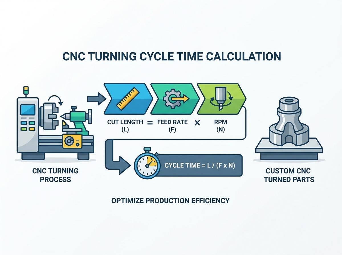
Estimators and machinists use exact equations for various turning operations to determine active cutting time. These formulas provide the baseline from which all other calculations are derived.
The core equation calculates the time required for a tool to travel a specific distance. The Imperial formula is T = [L / (f × RPM)] × 60 (seconds), where L is length of cut in inches and f is feed rate in IPR. The Metric formula is identical in structure: T = [L / (f × RPM)] × 60 (seconds), where L is length of cut in mm and f is feed rate in mm/rev.
Parameter | Imperial Unit | Metric Unit | Definition |
|---|---|---|---|
Length (L) | Inches (in) | Millimeters (mm) | Total distance of tool travel including approach. |
Feed (f) | Inches per Rev (IPR) | Millimeters per Rev (mm/rev) | Distance tool advances per spindle revolution. |
Speed (RPM) | Revolutions/Min | Revolutions/Min | Rotational speed of the spindle. |
Time (T) | Minutes or Seconds | Minutes or Seconds | Total active cutting duration. |
Consider turning a 4-inch length on a 2-inch diameter steel shaft. First, calculate RPM based on an optimal SFM, such as 350 SFM for medium carbon steel. Using the formula RPM = (350 × 3.82) / 2, we get 668 RPM. Next, apply the linear formula to determine the base cutting time for a single pass. Assuming a feed rate of 0.012 IPR, the time for one pass is T = 4 / (0.012 × 668) = 0.499 minutes, or roughly 30 seconds.
Finally, multiply this time by the number of passes required. If the raw material is 2.5 inches in diameter and the final diameter is 2.0 inches, you need to remove 0.250 inches of material radially. Based on a 0.100-inch roughing depth of cut, you need three passes (two roughing, one finishing). The total active cutting time is approximately 90 seconds.
Different operations require specific calculation adjustments to maintain accuracy. You cannot treat a drilling cycle the same way you treat a linear turning pass.
Facing Calculations: Adjust for variable diameters using Constant Surface Speed (CSS) and calculating average RPM based on the starting and ending diameters of the face cut.
Drilling on a Turning Center: Drilling time equals Depth / (f × RPM), incorporating the drill point angle and lead allowance into the total depth calculation to ensure the drill breaks through completely.
Threading Operations: Factor in multiple thread-cutting passes and acceleration/deceleration allowances for lead screw synchronization. Threading requires the spindle and Z-axis to be perfectly timed.
Grooving and Parting Off: These operations often require reduced feed rates as the tool approaches the center of the part to prevent chatter and tool breakage.
Addressing the gap between theoretical cutting time and actual floor-to-floor time is vital for accurate estimation. Non-machining variables represent hidden costs that can destroy profit margins if left unaccounted for.
Estimating time lost to turret rotation, indexing, and tool offset verification is necessary. This typically takes 1 to 5 seconds per tool index, depending on the machine's age and design. Utilizing multi-tasking machines or optimizing tool sequencing mitigates these delays. If a program requires ten tool changes, you could easily lose a minute of production time per part just waiting for the turret to spin.
Manual chucking takes longer than automated bar feeders and robotic load/unload systems. An operator manually loading a heavy casting might take two minutes, whereas a bar feeder advances material in five seconds. Amortizing setup time, which includes programming, jaw boring, and first-article inspection, across the total batch size provides a realistic per-part cost.
Calculate total setup time (e.g., 120 minutes for programming, tooling, and first article).
Divide setup time by the total batch size (e.g., 120 minutes / 500 parts = 0.24 minutes per part).
Add this amortized setup time to the individual part cycle time.
Factor in the manual load/unload time per part.
Include time for routine in-process inspection and chip clearing.
Account for the time it takes the tool to move from the home position to the clearance plane. Factor in the machine's specific rapid traverse specifications and axis acceleration or deceleration curves. These movements add seconds to every cycle. Older machines with slower rapid rates will inherently have longer cycle times than modern linear-guide machines, even if the active cutting parameters are identical.
Comparing evaluation methods for speed and accuracy helps determine the best approach for specific project phases. Both manual math and software simulation have their place in a modern manufacturing environment.
Manual calculations are best for quick, rough estimates during the early design-for-manufacturing phase. They allow engineers to quickly gauge the impact of a design change without needing to generate a full CAM program. However, they fail to account for complex toolpaths, constant surface speed variations, and acceleration curves, making them less reliable for final quoting.
Using built-in CAM simulation or dedicated estimating software provides higher accuracy. Software calculates dynamic RPM changes when facing parts and accurately models rapid movements based on specific machine kinematics. When you run a simulation in modern CAM packages, you get a time estimate that closely mirrors actual spindle time, assuming the post-processor is configured correctly.
Balancing the time spent programming a full CAM simulation against the financial risk of an inaccurate manual estimate is crucial. For high-volume production, the accuracy of CAM simulation outweighs the time investment. A five percent error on a manual calculation for a 10,000-piece run can result in massive financial losses. For a prototype run of five parts, the manual calculation is usually sufficient.
Actionable engineering decisions directly reduce machining time and part cost. The best way to lower cycle time is to design parts that are inherently easier to machine.
Trading off raw material costs against faster machining times is a common strategy. For example, machining Aluminum 6061 is significantly faster than 304 Stainless Steel, potentially offsetting a higher raw material price through reduced machine hours. Always consult machinability charts when selecting materials for high-volume components.
Excessively tight tolerances force slower feed rates and require additional finishing passes. Avoiding deep internal boring or custom threading that requires specialized, slow-feed tooling reduces cycle time. If a tolerance can be opened up from +/- 0.001" to +/- 0.005" without affecting part function, you eliminate the need for a separate finishing pass and reduce inspection time.
Designing parts that can be machined using standard insert shapes reduces tool changeover and indexing time. Standardized features streamline the entire machining process. Avoid specifying internal corner radii that require custom-ground boring bars. Stick to standard radii that match off-the-shelf turning inserts to keep feed rates high and tooling costs low.
Accurate CNC turning cycle time calculation must include more than the basic relationship between cutting length, feed per revolution, and spindle speed. Theoretical cutting time provides a useful baseline, but real production estimates must also account for multiple passes, tool changes, rapid movements, loading and unloading, inspection, setup, and machine-specific acceleration.
Manual formulas are suitable for early design reviews and rough cost comparisons. For complex parts or high-volume programs, CAM simulation provides a more reliable estimate by modeling constant surface speed, detailed toolpaths, and non-cutting movements.
Cycle time should also be treated as a design variable. Selecting machinable materials, avoiding unnecessary tight tolerances, simplifying deep internal features, and standardizing threads and radii can reduce machining time substantially. Reliable quotations should therefore separate active cutting, handling, setup, and inspection time.
A: The standard formula is Time (T) = Length of Cut (L) / (Feed per Revolution (f) × Spindle Speed (RPM)). Multiply the result by 60 to convert the output from minutes to seconds.
A: Drilling time is calculated by dividing the total drill depth, which includes the drill tip length allowance, by the product of the feed rate per revolution and the spindle speed: T = L / (f × RPM).
A: Non-machining time, including tool changes, rapid traverse, and part loading, can account for up to 40% of the total cycle time. Ignoring it leads to inaccurate cost estimates and unrealistic production schedules.
A: Material machinability dictates the maximum allowable spindle speed and feed rate. Harder materials require slower cutting speeds, increasing the total cycle time compared to softer materials like aluminum.
A: Use CAM software for accurate quoting and high-volume production runs. It accounts for complex toolpaths, constant surface speed variations, and rapid movements that manual formulas cannot accurately capture.


