


close
Choose Your Site
Global
Social Media
Author: Site Editor Publish Time: 2026-11-05 Origin: Site


Hydraulic manifold blocks function as the critical central nervous system for modern fluid power applications. Heavy machinery, aerospace systems, and advanced industrial automation rely entirely on these complex components to route fluid energy efficiently. Producing them correctly matters because substandard machining carries severe, immediate operational risks. Poor execution inevitably leads to internal pressure drops, localized leakage, and catastrophic valve failure. Even a single stray burr or a minor deviation in sealing face tolerances can shut down entire production lines and damage downstream equipment.
Producing reliable CNC machined hydraulic manifold blocks requires an exact science. Manufacturers must maintain rigorous alignment between intelligent CAM programming, advanced multi-axis machining capabilities, and uncompromising inspection protocols. In this guide, you will learn how internal geometry dictates fluid performance and system longevity. We will explore deep-hole drilling strategies, critical surface finish metrics, and the rigorous quality assurance standards you must verify before deployment.
Internal geometry dictates performance: Precise cross-hole intersections and automated deburring are non-negotiable for preventing fluid turbulence and system contamination.
Setup reduction is critical: Utilizing 5-axis CNC machining minimizes fixture changes, significantly improving datum alignment and positional accuracy across complex port layouts.
Sealing relies on surface metrics: O-ring grooves and valve mounting faces require strict adherence to surface roughness (Ra) and flatness tolerances to prevent high-pressure bypass leakage.
Verification is as important as production: Reliable manufacturing partners must offer transparent inspection data, including CMM reports, borescope gallery checks, and hydrostatic pressure testing.
Engineers design manifold blocks to handle extreme internal forces, often exceeding 5,000 PSI. Failure to execute these designs perfectly during the machining phase compromises the entire hydraulic circuit. Understanding these specific engineering stakes separates a functional prototype from a reliable field component.
Micro-burrs pose the greatest threat to fluid logic systems. When cutting tools break through intersecting galleries, they push material inward, leaving ragged edges. Under high fluid pressure, these micro-burrs snap off and travel downstream. They quickly reach sensitive proportional valves, actuators, and precision spools. A single metal flake measuring just 50 microns can jam a directional valve spool. This causes erratic actuator movement, complete system lockup, and destroyed pump internals. Poor intersection blending also induces fluid turbulence. Turbulence generates excessive heat, degrades hydraulic oil rapidly, and reduces overall system efficiency.
Selecting the right material influences both component weight and machining strategy. Each material presents unique manufacturing hurdles.
Aluminum (e.g., 6061-T6, 7075): Engineers favor aluminum for weight-sensitive applications and low-to-medium pressure systems. However, aluminum is gummy. It presents severe chip evacuation issues during deep-hole drilling. Continuous ribbons of material can pack inside the hole, causing tool breakage. Machinists must implement specific high-pressure coolant strategies to flush chips and prevent galling along the gallery walls.
Ductile Iron & Carbon Steel: High-pressure industrial systems demand ferrous materials for structural strength. These metals impose high tool wear rates. Dense port configurations remove significant material mass, weakening the block during machining. Facilities require exceptionally rigid machine setups to maintain dimensional tolerances. Without immense rigidity, cutting forces cause structural deflection, misaligning critical bore centers.
Procurement teams sometimes prioritize the lowest upfront machining quote. This approach usually backfires. Saving pennies on initial machining often results in massive warranty claims later. A poorly machined sealing groove might hold pressure during initial bench tests but fail under dynamic field cycling. When a block fails on an excavator or factory press, the resulting machine downtime costs thousands of dollars per hour. The financial impact of replacing destroyed proportional valves far exceeds the premium paid for high-quality machining.
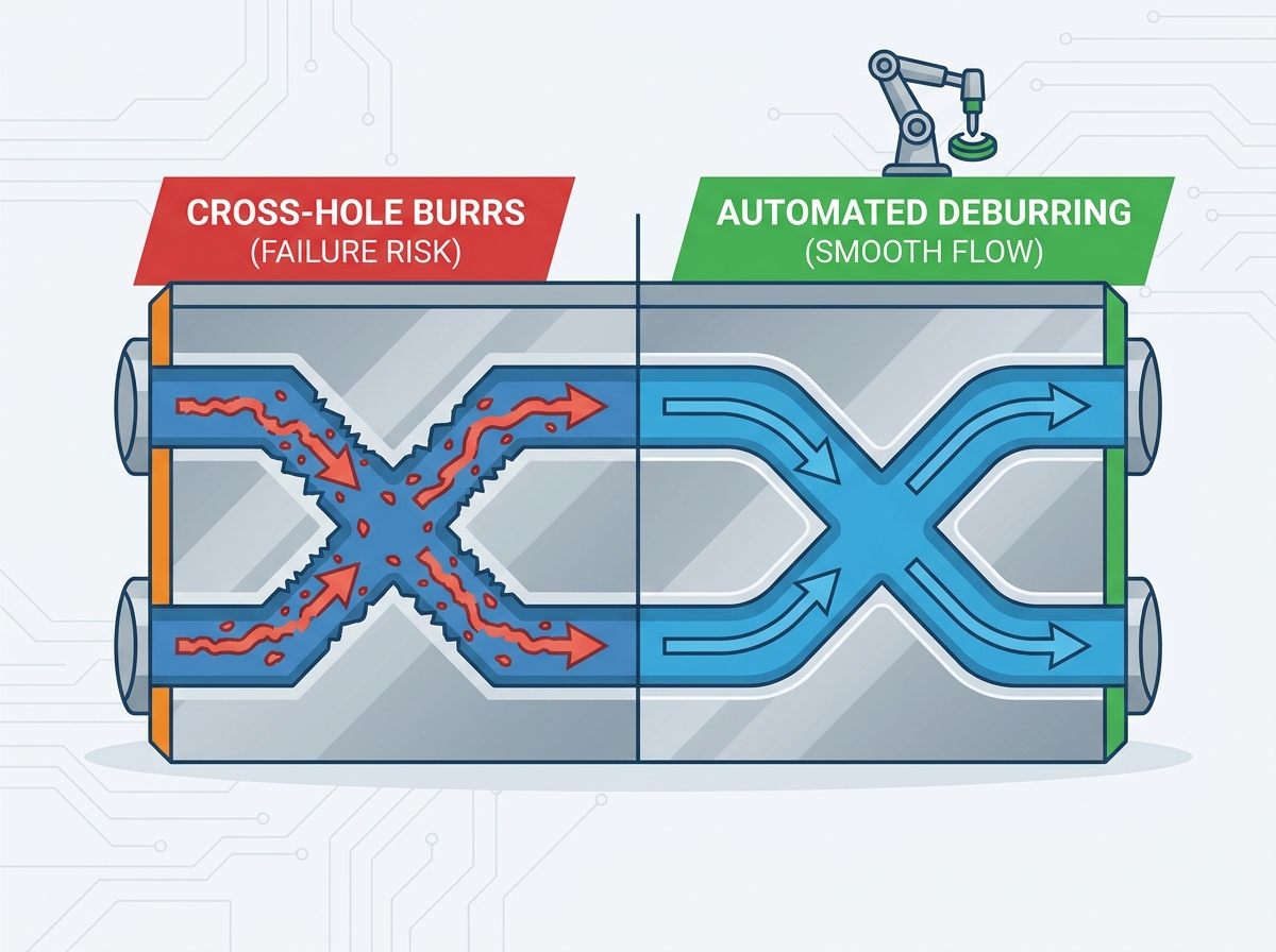
The complexity of a hydraulic manifold lies inside the block. Dense networks of fluid pathways must cross without breaking into adjacent, unintended circuits. Optimizing these layouts demands sophisticated software and specialized tooling.
Modern CAM programming bridges the gap between CAD models and physical reality. Programmers face immense complexity when mapping toolpaths for intersecting galleries. They must calculate precise feed rates and spindle speeds as tools transition across internal voids. When a drill breaks through into an existing perpendicular cross-hole, cutting resistance drops instantly. This sudden change can cause tool deflection. Programmers mitigate this by altering the feed rate precisely at the breakthrough point. This ensures clean intersections and prevents drill wander.
Hydraulic manifolds frequently require fluid paths that span the entire length of the block. Standard twist drills cannot handle depth-to-diameter ratios exceeding 10:1 without wandering off-center. Manufacturers must utilize specialized deep-hole drilling techniques.
Engineers specify gun drills and advanced through-coolant carbide drills for these operations. High-pressure coolant blasts directly out of the drill tip. This cools the cutting edge and forces chips up the flutes simultaneously. Maintaining concentricity and straightness in long internal fluid paths is crucial. If a deep hole wanders by just a fraction of a millimeter, it compromises the wall thickness between adjacent high-pressure galleries, leading to internal blowouts.
Deburring intersecting galleries is arguably the most critical step in manifold production. Manual deburring carries an unacceptably high risk of human error. Technicians using hand picks often miss hidden burrs located deep inside complex blocks. Industry leaders rely on automated processes.
Automated CNC Deburring: Specialized lollipop cutters trace internal intersection contours on the machine. This guarantees consistent edge blending based on programmed toolpaths.
Abrasive Flow Machining (AFM): Abrasive-laden polymer putty is forced hydraulically through the internal passages. The media polishes surfaces and rounds off sharp internal edges evenly.
Thermal Energy Methods (TEM): The block enters a sealed chamber filled with combustible gas. An electric spark ignites the gas, creating a micro-second burst of intense heat. This instantly vaporizes all thin burrs without altering the main block dimensions.
Comparison Chart: Deburring Strategies
Strategy | Precision Level | Ideal Application | Primary Limitation |
|---|---|---|---|
Automated CNC Tools | High | Shallow to medium-depth intersections | Tool reach limitations in very deep blocks |
Abrasive Flow Machining (AFM) | Very High | Complex, long, and winding internal galleries | Requires specialized secondary equipment |
Thermal Energy Methods (TEM) | Extreme | Blocks with dozens of microscopic cross-holes | High initial setup and equipment cost |
Fluid power systems do not leak through solid metal; they leak at connection points. The precision of external mounting faces and internal sealing grooves dictates system integrity. Without strict dimensional control, hydraulic fluid bypasses seals under high pressure.
Modular valves mount directly onto the manifold surfaces. Industry standards, such as ISO 4401 and DIN 24340, define strict mounting patterns. The flatness and parallelism of these mounting faces must remain flawless. If the mounting face bows or distorts by even 0.02mm, it creates micro-gaps. Under high dynamic pressure, fluid forces its way through these gaps, causing internal bypass leakage. Machinists achieve optimal flatness by taking ultra-fine finishing passes using large-diameter face mills.
Valves and cartridge inserts rely on O-rings to seal fluid ports. O-ring grooves require specific geometric dimensioning and tolerancing (GD&T). Gland profiles must prevent seal extrusion. If a groove is machined too wide, the O-ring deforms and extrudes into the gap during pressure cycles. The repeated mechanical shear shreds the seal. Surface roughness (Ra) must meet precise limits. If the groove bottom is too rough, it abrades the seal. If it is too smooth, it may fail to retain lubricating oil, causing dry rot.
Leveraging continuous 5-axis CNC machining revolutionizes manifold production. Traditional 3-axis machines require operators to manually flip and re-fixture the block to machine different sides. Each manual flip introduces slight datum shifts, creating dangerous tolerance stack-up errors. A 5-axis setup allows the cutting tool to access five sides of the block in a single clamping operation. It easily targets compound-angle ports that defy standard vertical machining. This setup reduction drastically improves positional accuracy across all external faces and internal bores.
You cannot simply assume a manifold block is flawless; you must prove it. Quality assurance in fluid power relies on empirical data. Comprehensive inspection protocols catch hidden defects before components reach the assembly line.
Coordinate Measuring Machines (CMM) act as the final authority on dimensional accuracy. Inspectors use highly sensitive touch probes to validate port locations, thread depths, and geometric relationships. The CMM software aligns the physical part against the native CAD model. It instantly flags any deviations in parallelism, true position, or hole concentricity. This automated verification guarantees every threaded port and dowel hole aligns perfectly with standard valve hardware.
CMM probes cannot verify what they cannot reach. Internal gallery inspection requires visual confirmation. Quality teams use articulating industrial borescopes to navigate deep cross-holes. Technicians evaluate the monitors to visually certify that intersecting paths remain 100% free of hanging burrs, swarf, and machining debris. Many aerospace and defense contracts require photographic evidence from these borescope inspections to accompany the final shipment.
Standard Machinability Properties Table
Material Grade | Typical Pressure Range | Primary Machining Challenge | Common Industrial Application |
|---|---|---|---|
Aluminum 6061-T6 | Up to 3,000 PSI | Stringy chips, risk of galling | Pneumatics, aerospace actuators |
Aluminum 7075-T6 | Up to 4,000 PSI | Deep-hole tool wander | Mobile hydraulics, robotics |
Ductile Iron (GGG40) | Up to 5,000 PSI | High tool wear, surface pitting | Industrial presses, heavy machinery |
Carbon Steel (1045) | Up to 10,000+ PSI | Thermal distortion, machine deflection | High-pressure hydraulic power units |
Visual and dimensional checks cannot confirm material density. Hydrostatic pressure testing verifies the structural integrity of the entire block. Technicians seal all ports and force test fluid into the galleries, often holding pressures at 1.5 times the maximum rated working pressure. This identifies hidden porosity within castings or billet stock. It also verifies that thin walls separating adjacent high-pressure galleries do not flex or rupture under extreme stress.
Even perfectly machined blocks must undergo rigorous cleaning. Contaminants like cutting fluids and microscopic dust ruin hydraulic oil. Facilities implement strict standard operating procedures for cleanliness. Blocks pass through multi-stage ultrasonic cleaning tanks. High-frequency sound waves dislodge any remaining particulate matter. Finally, operators flush the internal galleries with specialized rust-inhibiting fluids prior to vacuum sealing and final packaging.
Selecting a manufacturing partner involves more than comparing hourly shop rates. Hydraulic manifold production demands specialized equipment and deep tribal knowledge. You must evaluate potential vendors through a strict technical lens.
Examine the shop floor equipment closely. High-torque, rigid machining centers are absolutely mandatory for ferrous manifolds. The machines must feature robust spindle tapers (like CAT50 or HSK-A100) to dampen vibration. Crucially, look for high-pressure through-spindle coolant (TSC) systems operating at 1,000 PSI or higher. Without robust TSC, deep-hole drilling becomes a guessing game of chip clearing and tool breakage.
General job shops excel at simple brackets and enclosures. However, they often stumble on complex hydraulic blocks. A specialized partner understands fluid dynamics. They intuitively grasp hydraulic logic circuits. They know exactly why ISO 4401 mounting face tolerances exist and how to achieve them consistently. This domain expertise allows them to anticipate manufacturing bottlenecks during the DFM (Design for Manufacturing) phase, saving you time and money.
Clear communication accelerates production and ensures accuracy. When you are ready to request a CNC quote, supply comprehensive data packages. Do not just send a basic STEP file. Include 2D manufacturing prints that explicitly define critical-to-function dimensions and GD&T requirements. Clearly specify your material cert requirements (e.g., mill test reports). Outline any required NDT (Non-Destructive Testing) or hydrostatic test pressures upfront. This transparency ensures accurate quoting and a flawless first-article delivery.
Successful hydraulic manifold block manufacturing remains an exacting science. It demands a perfect balance between tooling rigidity, setup optimization, and exhaustive quality control. The integrity of your entire fluid power system rests on the microscopic tolerances held during the CNC machining process.
Actionable Next Steps:
Review your current CAD designs to simplify cross-hole intersections where possible.
Specify exact surface roughness (Ra) values for all O-ring sealing grooves on your 2D drawings.
Demand documented CMM and borescope inspection reports from your current machining vendors.
Evaluate your supply chain for 5-axis capabilities to reduce setup errors on complex blocks.
If you face tolerance stack-up issues, scaling bottlenecks, or persistent fluid leakage with your current components, it is time to upgrade your manufacturing strategy. Submit your 3D CAD files and detailed manufacturing prints today to secure a partner capable of executing your most demanding fluid power designs.
A: It drastically reduces setup changes. Traditional machining requires flipping the block manually to cut different faces, introducing tolerance stack-up errors. Continuous 5-axis machining accesses multiple faces and complex compound-angle ports in a single fixture, ensuring perfect datum alignment and reducing overall cycle times.
A: Cross-hole burrs are the biggest threat. When drills intersect internal galleries, they leave sharp metal flakes. If not meticulously removed and visually inspected via borescopes, these burrs detach under high fluid pressure, travel downstream, and destroy expensive proportional valves and actuators.
A: Aluminum grades (like 6061 and 7075) are common for lightweight, low-to-medium pressure applications up to roughly 3,000 PSI. Ductile iron and carbon steel are used for heavy-duty, high-pressure industrial systems that frequently exceed 10,000 PSI and require superior fatigue strength.
A: Manufacturers utilize highly rigid machine setups and specialized tooling like gun drills. Crucially, they employ high-pressure through-spindle coolant (TSC) to evacuate chips rapidly. Advanced CAM software also optimizes feed rates precisely at breakthrough points to prevent drill wander and deflection.


